
Description
- Six sizes to suit yachts up to 12m/40ft LOA
- Patented flexing spring provides fast response and a constant force for vang efficiency
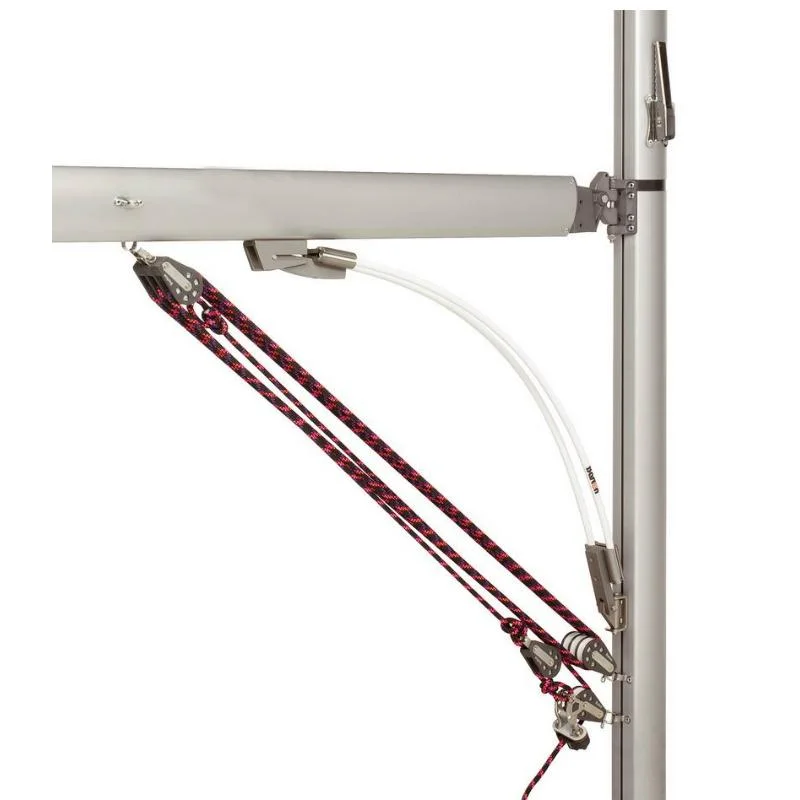
The boomstrut’s lightweight, low-profile design features two flexible coated fibreglass rods which provide the force to support the boom. Pulling the boom downwith a conventional kicker causes the Boomstrut to flex upwards; releasing straightens the rods, thereby lifting and supporting the boom. - Maintenance-free, durable design
Eliminates friction and sliding parts. - Improved performance
Less weight and windage - Easy installation
There’s no need to replace your existing hardware – the Boomstrut mounts independently inside the existing kicking strap tackle. - Simple-to-follow instructions
The Boomstrut is supplied with complete fitting instructions and more comprehensive details are available on our website, . - Mast fitting can use existing luff groove
To eliminate drilling, the Boomstrut’s mast bracket can be slotted into your mast’s luff groove. - Contoured boom fitting
The Boomstrut’s boom bracket is contoured to fit both round and flat boom profiles. - Carefully designed & constructed
The Barton Boomstrut has been carefully designed and constructed to eliminate sharp edges, minimise parts and provide trouble-free installation and use.All parts are from high-grade stainless steel and Spectro grey anodised aluminium for good looks and durability.
The Dinghy Boomstrut
- Ideal for:
Sailing Schools
Training Boats
Trailer Sailors
Cruising day boats - Maintenance free
- Fits in minutes
- No drilling required
With no extra parts or drilling required and is simply tied off at the mast to secure in place, negating the need for drilling. At the top of the rods, a fully adjustable webbing cradle supports the boom and as the cradle is not directly attached to the boom, it does not restrict the boom from rolling around its central axis to follow the sail when reefing.
| Compressed | Extended |
| Suggested boat length (m) | Part No. |
pin-to-pin length mm |
Max rods can be reduced by* mm |
Max initial full adjustment** mm |
Max stroke at full adjustment mm |
Force*** Kg |
|---|---|---|---|---|---|---|
| Barton Boonstrut | ||||||
| Dinghy | 44001 | 762 | 125 | 250 | 120 | 35 |
| Up to 6.0m | 44010 | 960 | 150 | 300 | 150 | 90 |
| 6.0 to 7.5m | 44020 | 1070 | 150 | 300 | 150 | 140 |
| 7.5 to 9.0m | 44030 | 1180 | 150 | 300 | 150 | 185 |
| 9.0m to 10.5m | 44035 | 1320 | 150 | 230 | 200 | 230 |
| 10.5m to 12m | 44040 | 1450 | 150 | 230 | 200 | 270 |
*The maximum amount the boomstrut rods can be shortened to fit inside the vang area.
**The maximum amount of available pin-to-pin travel when flexed.
*** The downward force the boomstrut will support at the point of the boom fitting attachment.
Boom strut – 44001 – Fitting Instructions
|
The Barton Dinghy Boomstrut is designed for sailboats under 5 metres (17′) with boom and sail tip weight of under 5 kgs(11 lbs). We recommend, after reading the instructions fully, that you should install the complete system, then determine if the rods require cutting. This would mean the strut position may not be correct but will allow you to measure the downward force required (with sail flaked) on the aft end of the boom to flex the rods. Units with rods which have been shortened will not be exchanged, so be sure that the strut is suitable before doing so. You may need to upgrade to the 44009 web strut if the 44001 dinghy strut does not support the boom. |
||||||||||||
| The Dinghy Boomstrut assembly | ||||||||||||
|
THANK YOU FOR CHOOSING THE BARTON DINGHY BOOMSTRUT. INSTALLATION IS A FAIRLY STRAIGHT FORWARD OPERATION AND CAN BE ACHIEVED IN A RELATIVELY SHORT TIME FOLLOWING THESE FITTING PROCEDURES: |
||||||||||||
|
RECOMMENDED INSTALLATION TOOLS: Cross-headed Screwdriver, Fine Tooth Hacksaw, Ruler, Pencil |
||||||||||||
|
SET UP BOOM HEIGHT: Use the main halyard or support the boom above its highest operating position. This would usually be between 15cm (6″) and 20cm (8″) above the horizontal at the outboard end (see fig. 1). The web strap sits under the boom in front of the kicker attachment point. The maximum weight it can support is 5Kg (11 lbs) measured at the end of the boom with the sail flaked. |
||||||||||||
|
||||||||||||
|
POSITION BOOMSTRUT: The Boomstrut works by flexing upwards; when straight, it is at the top of its travel. Install the Boomstrut with the mast swivel bracket screw head side facing downwards and the webbing cradle eye facing forward. With the boom height set as above and the mast and boom web strap fitting attached to the Boomstrut, position it alongside the vang triangle to see how it fits. Position is not critical so long as it does not interfere with the vang (kicking strap). It is recommended that both the vang and Boomstrut make an angle of between 30 and 40 degrees with the boom. The Boomstrut is designed to fit inside your current vang (kicking strap) tackle, but in some cases it may be necessary to reposition attachment points of these blocks to allow sufficient room. At this point mark the location for the mast fitting. |
||||||||||||
|
INSTALL MAST FITTING: If the position of the gooseneck can be adjusted whilst sailing, mark the lowest point, then slide the Luff groove slide down the luff groove from the sail opening, this may require disassembling to allow the luff groove slide to slide behind a fixed gooseneck. This can be achieved be placing a screw driver into the luff groove below the gooseneck and sliding the slide downwards until it sits on the screw driver then rotate the slide until the threaded hole is visible, now screw in one of the mast bracket screws, this will allow you to hold the slide in position until you fix the mast bracket back on to the slider. When the slider and mast bracket is loosely in position slide the gooseneck to its lowest mark. Always use a |
||||||||||||
|
INSTALL WEBBING CRADLE Ensure the web cradle eye and line are facing the mast. |
||||||||||||
|
INSTALL LUFF GROOVE EYE Use the “install mast fitting” to install the luff groove eye and secure just below the lowest point of travel of the gooseneck or approx 5 cm below the fixed gooseneck. |
||||||||||||
|
SHORTEN RODS IF NECESSARY: If the Boomkicker is too long or the angle too low, it can be cut down. Shorten the bottom of the rods (loosen two small screws in base to pull the rods out) equal lengths of no more than 5″ (130mm). A fine tooth hacksaw works best and frayed ends can be avoided by pre-wrapping a layer of tape around the rod at the cut. IMPORTANT: Do not shorten the total lengths of the rods by more than 130mm. |
||||||||||||
|
INSTALL BOOM FITTING: Ensure that the rod clamps are tight at the mast end. With the Boomstrut in position, lift the boom 20cm above horizontal and tie off the webbing strap tensioner line tight to the gooseneck fitting (Fig no.1). Pull on the kicker to compress the rods and level the boom. When sailing, adjust the kicker to suit the sailing conditions in the normal manner. |
||||||||||||
|
FINAL CHECKS: After installation, check the return force by pushing down on the end of the boom. Excessive return force will cause the boom to bow. For reference, with the sail flaked, only approx. 3.5kg (8lb) should be needed to pull the end of the boom down. |
||||||||||||
|
Should you have any questions with regard to installation of your Boomstrut please contact your Chandler in the first instance. |
||||||||||||
Reviews
There are no reviews yet.